Harbor Freight Tools 95607 User Manual - Page 10
Assembly Instructions
 |
View all Harbor Freight Tools 95607 manuals
Add to My Manuals
Save this manual to your list of manuals |
Page 10 highlights
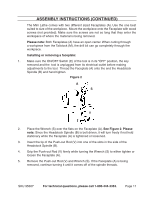
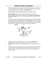
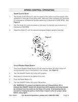
Assembly Instructions Note: For additional information regarding the parts listed in the following pages, refer to the Assembly Diagram near the end of this manual. 1. WARNING! Make sure the Power Switch of the Lathe is in its "OFF" position and that the Lathe is unplugged from its electrical outlet before making any adjustments to the Lathe. 2. Mount the Lathe on a benchtop by first measuring and marking three hole centers. See Figure 1. 3. Drill holes through the marked locations. Be sure there are no hidden wires. 4. Install the bolts and washers (not included) from under the benchtop and into the holes in the bottom of the Lathe frame. Please note: To hold the Lathe securely, the bolts must be a minimum of 1" into the frame. Figure 1 5. The spring-loaded lock levers for the Tailstock Spindle (N) and the Tool Rest (L) are made of separate parts. If either lock lever has come loose during shipping, they must be reassembled. Spring Shoulder Screw 6. To reassemble a lock lever, the shoulder screw passes through the spring and the handle lever and then into the Tailstock Spindle and Tool Rest, as shown in Figure 2. Handle Lever Figure 2 SKU 95607 For technical questions, please call 1-800-444-3353. REV 07l Page 10
-
 1
1 -
2
-
3
-
4
-
 5
5 -
 6
6 -
 7
7 -
 8
8 -
 9
9 -
 10
10 -
 11
11 -
 12
12 -
 13
13 -
 14
14 -
 15
15 -
16
-
17
-
18
-
19
-
20
 |
 |
